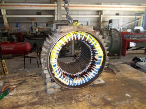
Three three-phase induction motor is the most popular of all motor type because, it has a high power factor, which means high efficiency, and they are self-started no capacitor is needed.
A 3-phase induction motor is an electric motor that is designed to work on a 3-hase power supply and needs no starting capacitor like a 1-phase induction motor.
Table of Contents
Induction Motor Parts
It’s important to understand the construction of a 3-phase induction motor to get a good understanding of its principle of working
This motor consists of two main parts
- Motor stator
- Motor rotor
3-Phase Induction Motor Stator
The stator is made of slots to construct a winding circuit which is connected to a phase electricity source.
The three-phase winding is arranged to produce a rotating magnetic field when connected to a power source.

The rotor of the induction motor
Rotor is the rotating part of the motor, that is connected to the mechanical load.
It’s a cylindrical laminated core with parallel slots that can carry conductors.
The conductors are short-circuited by end rings and are made of copper or aluminum fitted in the slots.
Induction Motor Working Principle
Creation of the Rotating Magnetic Field
The motor’s stator contains windings that, when connected to a three-phase AC supply, generate a rotating magnetic field. The three-phase current in the stator windings creates magnetic fields that are 120° apart in phase. These fields combine to produce a single rotating magnetic field.
Induction of Current in the Rotor
The rotor (either a squirrel cage or wound type) is placed within the stator’s magnetic field. Since the rotor is initially stationary, the relative motion between the rotating magnetic field of the stator and the rotor induces an electric current in the rotor windings via electromagnetic induction.
Generation of Torque
The induced current in the rotor generates its own magnetic field, which interacts with the stator’s rotating magnetic field. This interaction produces torque, causing the rotor to turn in the same direction as the rotating magnetic field. The rotor tries to catch up with the synchronous speed (speed of the stator field) but can never reach it due to “slip” — a necessary speed difference for induction to occur.
Advantages and Disadvantages of a Three-Phase Induction Motor
Advantages:
-
Simple and Robust Construction
- Induction motors have a simple design with no brushes or commutators, which makes them durable and less prone to mechanical failures.
-
High Efficiency
- They offer high efficiency (up to 97%), especially under full load, which helps reduce operational costs.
-
Self-Starting Capability
- Unlike single-phase motors, three-phase induction motors are self-starting and do not require additional starting mechanisms.
-
Low Maintenance Requirements
- The absence of brushes and slip rings reduces maintenance needs and operational costs.
-
Good Speed Regulation
- They maintain a nearly constant speed under varying load conditions, which is ideal for industrial applications.
-
Cost-Effective
- Their simple design and widespread use make them economical for both purchase and operation.
-
Ease of Rotation Reversal
- The direction of rotation can be easily reversed by swapping any two of the three-phase connections.
Disadvantages:
-
High Starting Current
- They draw a high inrush current at startup, which can cause voltage drops and affect other connected equipment. Starting methods such as star-delta starters or soft starters are often required.
-
Limited Speed Control
- Induction motors are constant-speed machines. Adjusting their speed requires external devices like Variable Frequency Drives (VFDs).
-
Lower Power Factor at Light Loads
- When operating under light loads, their power factor decreases, which can lead to inefficiencies and increased energy costs.
-
Poor Starting Torque
- The starting torque of squirrel cage induction motors is lower, making them unsuitable for applications requiring high initial torque.
-
Slip Dependency
- The rotor speed always lags behind the synchronous speed, introducing slip, which can limit the motor’s performance in some applications.
I highly recommend Reading My Articles, Star Delta Starter of Motor.
Applications
These motors are commonly used in industries for driving equipment such as pumps, compressors, conveyors, and fans due to their reliability and efficiency
Motor Speed Control and Formula
The speed formula of this motor is N = Ns(1-S),
while Ns = (120 f)/P
Where :
- Ns is the synchronous speed.
- f is the frequency.
- P is the number of poles of the motor.
controlling the motor speed can be done by one of the following methods
- Frequency control or (V / f) control.
- Number of poles Changing
- Voltage Controlling.
Read My detailed article: Electric Motor Speed Formula, Calculator and Control
Motor Current Calculator
The current formula for a 3-phase induction motor is, I = P/(1.73*V*pf)
Where,
I: Motor current
P: Motor power in Watt
V: Motor operating voltage
pf: Motor power factor
You can find the motor’s data, voltage, power, and pf, on the motor nameplate. I have written a detailed article about Motor Name Plate, You Can Find It here, for more information.
If we don’t know the power factor of the motor, we assume it’s 0.85
I designed my Android app to be easy and help you so, no matter what motor power you have KW or HP, the app converts it to watt internally.
What Causes An Electric Motor to Start Slow?
A slow-starting electric motor can result from several potential issues. Here are some common causes:
Low Supply Voltage
- If the supply voltage is lower than the motor’s rated voltage, the motor may struggle to generate enough torque to overcome inertia, causing it to start slowly.
High Load on Startup
- Motors under excessive load during startup may not generate sufficient torque to reach their operating speed promptly. This is common in applications with heavy or jammed machinery.
Faulty Start Windings or Capacitor (in Single-Phase Motors)
- In single-phase motors, issues with start windings or a defective start capacitor can lead to slow or failed startups.
Worn Bearings or Mechanical Binding
- Mechanical issues like worn or seized bearings can increase friction, impeding the motor’s ability to start smoothly.
Electrical Connection Problems
- Loose or corroded electrical connections can cause voltage drops, reducing the motor’s performance during startup.
Motor Overheating
- An overheating motor from previous use or poor ventilation may have damaged windings, leading to reduced efficiency and slow starts.
Faulty Rotor or Stator
- A damaged rotor (e.g., broken bars in a squirrel cage rotor) or a fault in the stator windings can reduce the magnetic field strength, slowing down the motor’s startup.
Improper Motor Sizing
- A motor that is undersized for the application may struggle to handle the load, resulting in slow acceleration.
External Starting Device Issues
- Problems with external devices like soft starters or star-delta starters can also impact the motor’s startup performance.
- Low resistance: Low resistance causes degradation of insulation flux. As a result, it will cause overheating and flux leakage and the motor will start slow. It is worth mentioning to discuss overheating. Overheating is the main cause of motor failure and slowdown.
What Happens If An Electric Motor Loses Power Under Load?
Three-Phase Loss:
Electric motors are designed to rotate freely with the assistance of bearings, allowing safe deceleration in the event of a complete power loss (i.e., loss of all three phases). When this occurs, the motor continues to spin under the momentum of the connected load, gradually slowing down until it stops.
Power in an electric motor is a product of current and voltage. If power is suddenly cut, the motor loses its ability to maintain the electromagnetic field in its windings, leading to a gradual reduction in induced EMF (electromotive force) and flux. Eventually, this causes the motor to come to a complete stop.
Single-Phase Loss:
If one phase of a three-phase motor is lost while the motor is under load, it will continue to operate but at a reduced speed. However, this creates an imbalance, leading to a significant increase in current in the remaining two phases.
Without phase loss protection, this excessive current can overheat the motor windings, ultimately causing them to burn out. Phase loss protection devices are crucial in preventing such damage by shutting down the motor when a phase loss is detected.
Don’t Leave Empty-Handed!
Install my Free Android App on Google Play:
Electrical Cables Most Common Tables “Cables Tables”
And, my Electrical Calculations App “Fast Electrical Calculator”
Discover more great content by subscribing to My channel
Looking to stay ahead of the game in the world of electrical engineering? Subscribe to my YouTube channel and gain access to exclusive content you won’t find anywhere else!
The staff I recommend
(Amazon Affiliate Links to products I believe are high quality):
- Economy 120 Volt/60Hz AC Power Source – Step-Down Voltage & Frequency Converters 1800W
- UNI-T Digital Multimeter Tester UT139C
- 50-Amp Extension Cord for RV “100ft”
- Voltage Stabilizer 110/220v
- Hair Dryer “best selling“
- TOSHIBA EM131A5C-BS Countertop Microwave Ovens
Disclaimer: This contains affiliate links to Amazon products. I may earn a commission for purchases made through these links.

